
Mach3 has only 1 probe input available. So if you have the corner finding plate set up on the machine and you want to connect a touch probe, you will need to make a simple circuit to invert the signal so that you can have both a normally connected and normally closed inputs on the same pin.
I have used transistors before in other projects, but because there are no schematics available for the break out board in the plug-n-play kit, I had to do some experimenting. I took pictures of everything so that I could grab the model numbers off of the chips I could see. The Ethernet smoothstepper has 5v tolerant pins. The Break out board has 12v inputs and outputs. A optocoupler is on every input to allow the 12v to signal the 5v without destroying it.
This all came together in a forum, but this post is to reconcile the relevant information. That and I can look at this for info in the future. Here is the forum thread link.
Supplies used:
-
1 1K resistor
-
2 10K resistors
-
M12 field wire-able connector, female. I had a few M12 pigtails in my stock already
-
Hookup wire
-
Some sort of PCB to connect everything, unless you want to try and deadbug the circuit.
-
2N2222a transistor - $5.97 for 200 of them at amazon
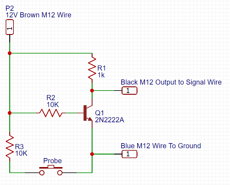
Bear in mind that the break out board optocoupler has a 1.2K resistor on the input. That being said, I still have a 1K resistor on the output of the transistor because I thought it would be floating without it. It should be fine without that resistor, because the input should do the work of pulling the input down. However, the circuit still works fine and since it was working, I did not change it.
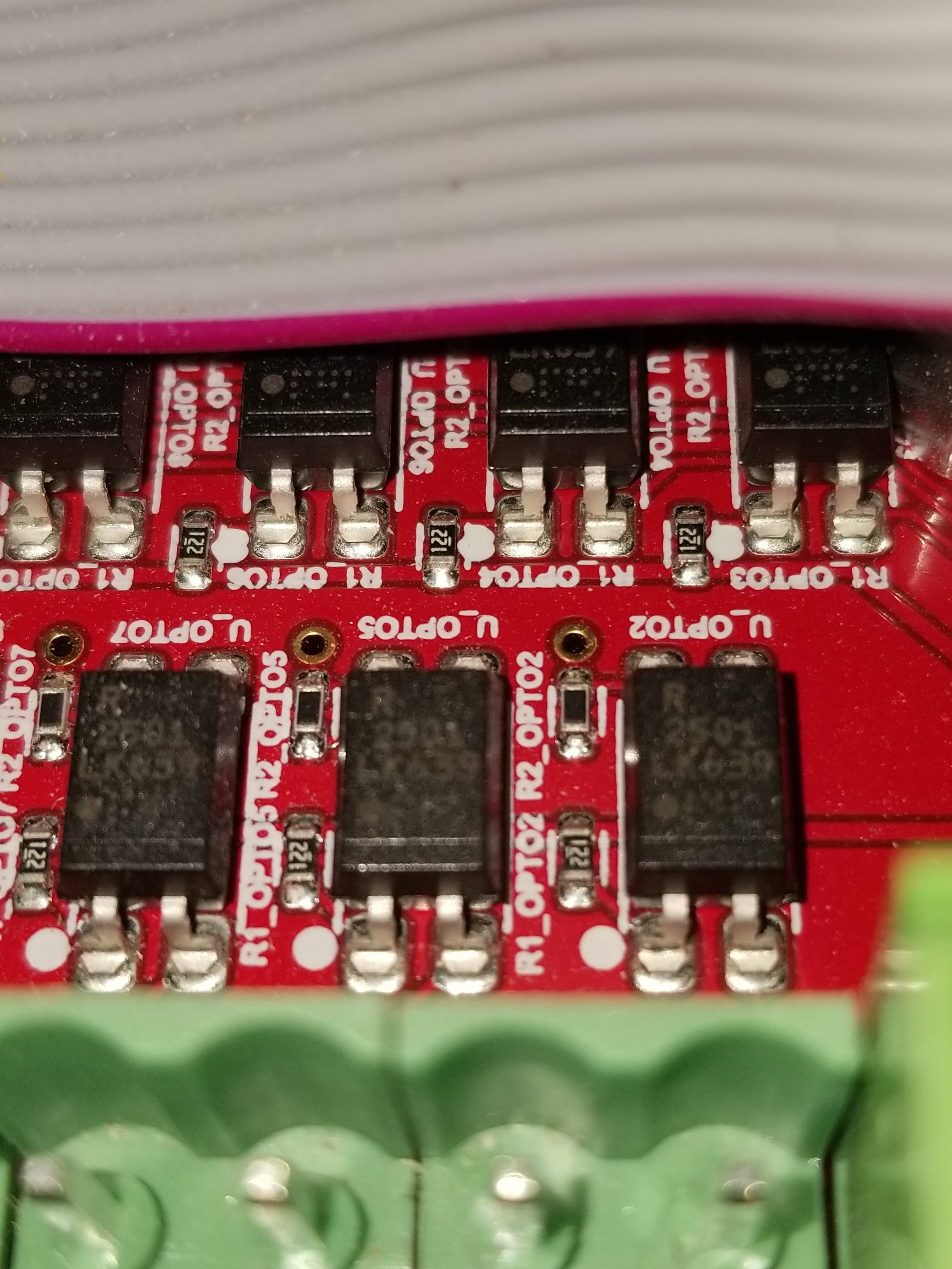
2501 optocoupler and 1.2k resistor
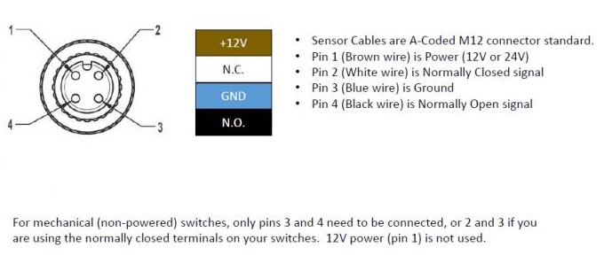
The input M12 connectors are wired based off of standard M12 colors.
Black is the normally open input wire. On the touch plate this is the wire connected to the body inside with a spade connector.
Blue is the ground wire . On the plate it is connected to the red ground clip wire.
Brown is the 12V output available. On the plate, it is cut close to the end of the wire. You will need to remove the wire bundle and remove the sheath enough to expose as much as is needed.
White is the normally closed input connection. This is unused in this project. However, if you do not have a touch plate, you can use this as the input as normally connected without an inverter.
When I wired my setup, I decided to run a pigtail out of the touch plate. The circuit board is attached to the end of my probe wire bundle. If you were to keep the circuit connected and just disconnect the probe, then the signal would always be on. You could bypass this by adding a switch to connect the probe signal pins while disconnected. It was easier to leave it out when I disconnect. Plus, the pigtail takes up little room and extends the probe connection beyond what the touch plate can reach.
I am thinking about ordering a few boards from JLCPCB with the circuit set up on it. I may add several of the circuits, with switches to change each input from normally closed to normally open when needed. This way you could have as many plates and probes as you want available on the one port. Then either machine, 3D print, or use an off the shelf project box to add M12 in and out ports. 1 to connect to the break out board and as many inputs as you would want on the other side. Mount this to the case, or to the frame of the CNC to easily extend Machs limited probe input.
The whole reason for me needing this, originally, is to use with my 4th axis. So far I have been basically eyeing the alignment and doing some rough calculations to get to center. With the probe, I can write a macro to measure the distance between two sides of a known shaft, then divide for center. Touch off of the top of said center and then divide the known shaft diameter in half to set the Z zero location. I can then make sure the other side is aligned as well as it can be and verify this. I could also use some macros that exist out there to account for any offset in the x alignment and not have to fine tune the physical position of the other end. The G-code could just account for the deviation in alignment.
The next goal, now that the probe is working, is to switch over to the 2010 screenset. I have been wanting to do this for over a year and did not understand how to set it up until recently. After playing with things in mach in simulation mode, I am fairly certain everything will work out. I also started modifying the screenset with my own buttons and whatnot. This could get out of hand. I am going to try and converge several screensets that have great macros within them, but do not work together. One for probing in the 4th axis to create point clouds of objects to wrap designs around. The squirrel probe screenset with 4th axis point cloud digitizing is in the forums here.
This is a nice set of macros, but is for the default screenset. It will take lots of time to convert and add it to my screenset setup. After playing with it I will probably devote the time. No idea when, could be another year. One other thing that I need before I can use it is homing on the 4th axis. I think I can accomplish this in a few different ways. I could use an optical encoder with 1 slit at 0 and rotate until it triggers. Having homing, after reading about it, makes sense on the 4th. Being able to repeat location instead of just setting whatever current angle to 0, would allow for mounting different types of workholding, like tombstones. Not to mention I could recover from a crash or something much easier than attempting to reset zero position after the fact. This will come in time, too many other things to do at this point. Seems like I spend most of my time creating tools instead of using them. I need to start using them more.
Just to make sure this information is not buried in the forums, I need to add this here. The 2010 screenset requires that the Z 0 position is located at the inverted values of the CNCRouterPrts setup. This means that the machine location of soft max needs to change from 8 to 0, soft min from 0 to -8 and I am pretty sure slow zone needs to invert to -1. Then the macros should work. I also created a button on the screenset to run the NCRouterParts corner finding plate macro. First I made it a macro that could be called with M997 and then used the button to run the M997 command. Now everything that was available in the default screenset, is available in 2010. I used machscreen to make the modifications.
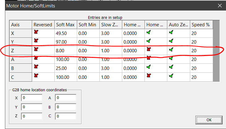
Original homing from CNCRouterParts
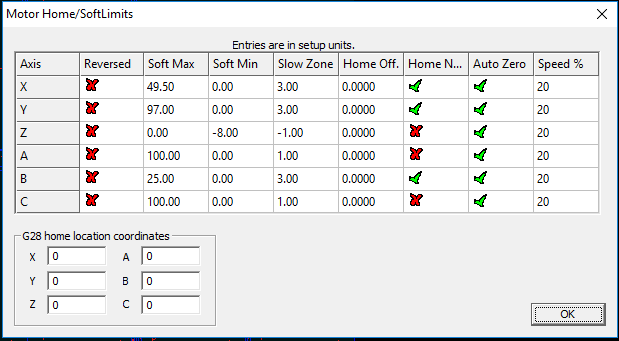
Changes for 2010 screenset
This should be enough information to move forward. Enough documenting, I need to finish cabinets….


Leave a comment